| |
 |
![]()
Merlin told me that he had successfully produced colloidal silver with DC voltages ranging from 5-130 volts. Therefore, in an emergency situation, you only need a single 9 volt battery (Mallory MN 1604) and 2 pieces of pure silver wire to make colloidal silver. Everything else mentioned in this section on generator construction is useful and convenient, but not essential.
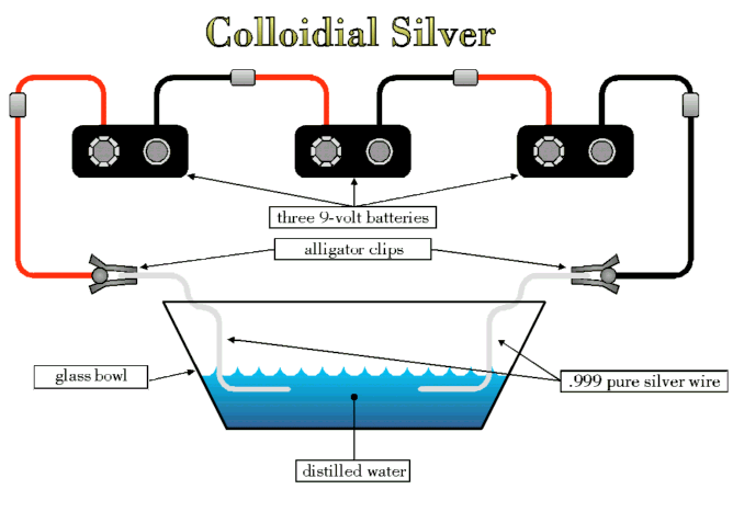
A typical generator uses three 9 volt batteries hooked up in series because it works well, it’s convenient, and provides a high enough voltage that allows the reaction to take place in a reasonable span of time (lower voltages would require more time to make an equivalent batch of colloidal silver. Higher voltages work too, but you get a more rapid buildup of the silver oxide on the positive anode, and somewhat larger particles). In a pinch, you could connect your batteries with ordinary hookup wire, but using three of those snap-on caps with wire pigtails designed for 9 volt batteries is much easier (Philmore Battery Connect, 3" Leads-9V. Flat, No. BC9). You can buy a package of 5 snap-on battery connects with wire leads at any electronic store for a buck. The red wire coming off the snap-on is connected to the positive terminal of the battery and the black wire is negative. For convenience, we’ll label our batteries A, B, and C.
The simplest (and cheapest) set up is as follows, resulting in a circuit configuration that looks like figure 1:

A more sophisticated generator design could include the following:
(For those who tinker with electronics, you could always add more bells and whistles like an a/c adapter, low battery voltage indicator, current limiting circuitry, etc.)
This information is for educational purposes only and is not to be construed as medical advice. Consult the physician of your choice for medical care and advice.
Offered by Ed
Graphic by Joe.